Parallel Rlc Phasor Diagram
13+ phasor diagram parallel rlc circuit Using phasor diagrams to evaluate series and true parallel rlc ac Phasor rlc circuit
Driven RLC Circuit Using Phasors – GeoGebra
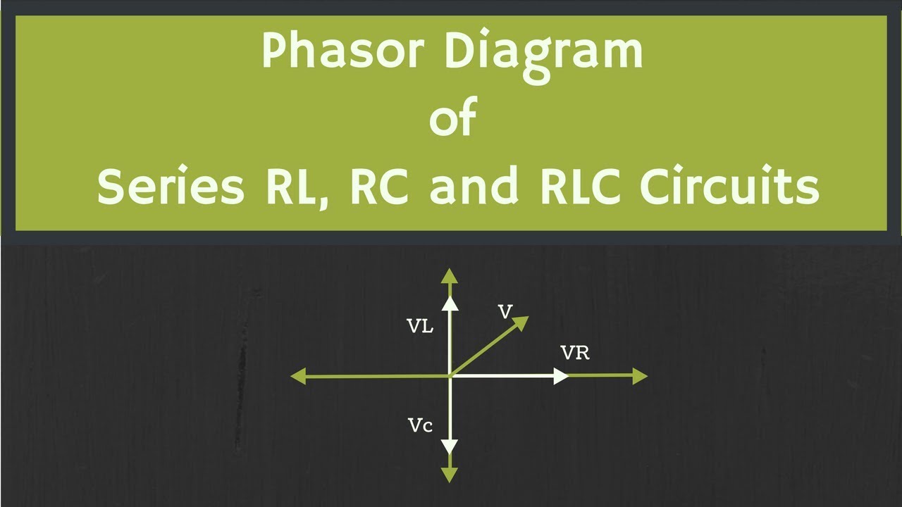
13+ phasor diagram parallel rlc circuit Phasor diagram of rl, rc and rlc circuits (with examples) What is rlc series circuit?
Circuit rlc geogebra resonance frequency driven phasors using
Phasor rlc parallel series ac circuits diagrams usingWhy is the inductive reactance or capacitive reactance phasor on the Phasor circuit rlc series diagram voltage current ac power draw phase impedance triangle reactive angle phasors physics lagging length whenPhasor circuit parallel rlc circuits diagram reactance analysis electronics voltage series capacitive inductive capacitor electrical inductor engineering axis vectors reference.
Phasor diagram rl rc rlc circuits examplesPhasor circuit rlc series diagram voltage current ac power draw phase impedance triangle reactive angle phasors length compressor physics steps Driven rlc circuit using phasors – geogebra13+ phasor diagram parallel rlc circuit.

Phasor rlc parallel
Phasor rlc parallel circuits .
.